About this site

Featured

Welcome to my Series Land Rover site, it covers a broad range of ongoing work to my 1982 ex MOD 109 that I have owned since 2006.

The site is in Blog form but you can choose from categories on the right hand side >>>>

If would like to contact me for whatever reason please use the ‘Contact Me’ tab above.

I’m situated in West Yorkshire, UK.

Series 3 Land Rover


Chassis Bush removal puller

I’ve just replaced the front passenger side spring chassis bush ready for the MOT test tomorrow. These bushes are notoriously difficult to remove , I’ve heard many stories of people setting fire to them and then hacksawing the outer sleeve for hours to try and get them out.

I’ve found replacing these to be a straight forward job with the right tool. I’ve made a puller pusher by cutting up a scissor jack and using the coarse threaded bar and the ends of the jack. A tube with a 40mm internal diameter that is just a bit longer that then bush is also required to draw the bush into. The diameter of this tube is important as the kinetic force should be applied to the tube the bush is sitting in rather than the chassis rails.

Make sure a decent quality scissor jack is used with steel ends as I’ve seen some with plastic ends. It’s also an idea to lube the coarse thread with engine oil.

Chassis Puller Tool

I simply used the new bush to push the old one out. A 22mm socket fits over the steel eye allowing a ratchet to be used.

The worn bush pictured below was last changed 18 years ago!

Chassis bush

Refitting Inner Wing Mudshields

Just got a few things left to finish before taking the 109 for it’s first MOT in 3 years. I’ve just fitted the inner wing mudshields in place, the bottom end of these are usually bolted directly to the footwell of the bulkhead however the area where the mudshield meets the footwell tends to be a rot trap as all sorts of soggy things end up stuck down there like soggy leaves and mud etc.

To avoid this happening I’ve used some 10mm nylon spacers to open up enough space for water, leaves mud etc to drop through to the floor instead of getting stuck there.

Replacing Detent/Synchro Springs In A Series Land Rover Gearbox

I’ve just replaced all three 3rd/4th gear synchro springs in the gearbox with the gearbox still in place in the vehicle. There is already a guide kicking around online on how to do this, stating that the seatbox needs to be lifted four inches, however I can confirm the seatbox does not have to be moved at all. 

The reason for lifting the seatbox appears to be the space needed to lift the gearbox top cover over the two studs highlighted in the image. However these 3/8 UNF studs can be removed by using two ‘half’ nuts locked together and unwinding the the stud out of the case. There is not enough stud showing to get two standard nuts on. Once these two studs are removed the gearbox top cover does not need any ‘headroom’ when lifting off and therefore the seatbox does not need moving at all.

Engage 3rd gear and then remove the gearstick.

Carefully remove the two brackets on either side that hold the springs against the detent balls. Once you’ve removed the brackets and the springs, dab a little grease in the holes to stop the detent balls rolling out and disappearing.

Once you’ve unwound the 3/8 studs mentioned above (3319) then you can remove the gearbox top cover. Make a note of where the detent balls are situated before removing them. There is a spring under the large central bolt (556570) so be careful it doesn’t pop out when removing.

Now you need to lift the selector rods off, before you do make sure you note where the selectors sit in the gearbox. Lifting them out takes a bit of wiggling but it is straightforward.

Once the selectors are out of the way you will have a good view of the 3/4 Syncro unit. Put the transfer box in neutral and you can turn the gears and see where the spring/s are missing. In my case all three springs were missing, I’ve been double de clutching for years, had I known it was these easy to replace the springs I would have done it years ago.

Push the middle selector plate of the synchro all the way forward toward the bellhousing. At this stage you will need some long reach long nose pliers with a 45 degree angle.

Using the pliers, try to push the end of the spring through the small rectangular space in the centre of the synchro where the spring should sit. At this stage I had to use a long thick leather needle with a wooden handle that I used to prod the end of the spring through while wiggling the spring into place with the pliers. It is a very tight angle, I don’t think I would have been able to get the spring through without pushing at one end and wiggling the other.

Once the end of the spring is through the hole and the spring is in line but not pushed all the way across into place, pull the middle selector plate backwards over the spring and the spring will then click into place. You may need to use the pliers to lever the middle of the syncro over as it is quite stiff once the springs are fitted. Make sure to check the end of the spring is correctly in place at the forward end as it may need another prod over the lip.

The first spring took me a while, however the other two were a doddle once I’d understood how to do it.

Refitting is a just a reversal of removal. The below image will assist with refitting the sector forks in the right place.


New Injection Pump

Further delays – after the rebuilt engine back in the vehicle I could not get it to start. I was not getting fuel to the injectors, it’s unusual to get an air lock in the 200tdi fuel system as they self bleed however I thought that it must have air in it somewhere. I used a pump to suck diesel back through the return pipe and tried to start again – this time the engine fired up but at full throttle. I tried a few more times but just got the same result. The weights in the fuel pump are at full throttle when resting, a design to aid starting and the reason for the famous black puff of smoke whenever a 200 starts. Mine had got siezed due to the pump being off the vehicle for 12 months and stored without diesel in it, apparently they corrode VERY quickly internally if not vacuum sealed. Lesson learned. I took the pump to a diesel specialist and there were a few other issues (including a previous owner forcing a imperial thread banjo bolt into a metric thread on the case!) that rendered the pump a write off. The diesel specialist offered me a rebuilt pump for £300 that would be ready in a couple of weeks.

In the meantime I purchased another 200tdi complete engine for £300 in the hope that the injection pump was ok, I wouldn’t need the refurbed one and I’d also have a whole engine for spares. This spare engine had come from a Range Rover Classic but had also been sat in a garage for a long time so it would be a long shot that the pump was running ok. I fitted the pump from that engine, however it would only idle for a few seconds before stalling and it idled roughly. So i removed that and in the end bought and fitted the refurbed pump and that one runs like a dream.

I’m stripping the Range Rover engine, so if anyone needs any 200tdi engine parts let me know!

Range Rover 200tdi Engine


Series Land Rover Wiring Colours

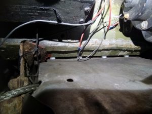
I need to tidy up some of the wiring in the engine bay as there has been a lot of bodges in the past. There are all sorts of wires that have incorrect colour codes in there that go nowhere and I’ll be pulling everything out and starting again.

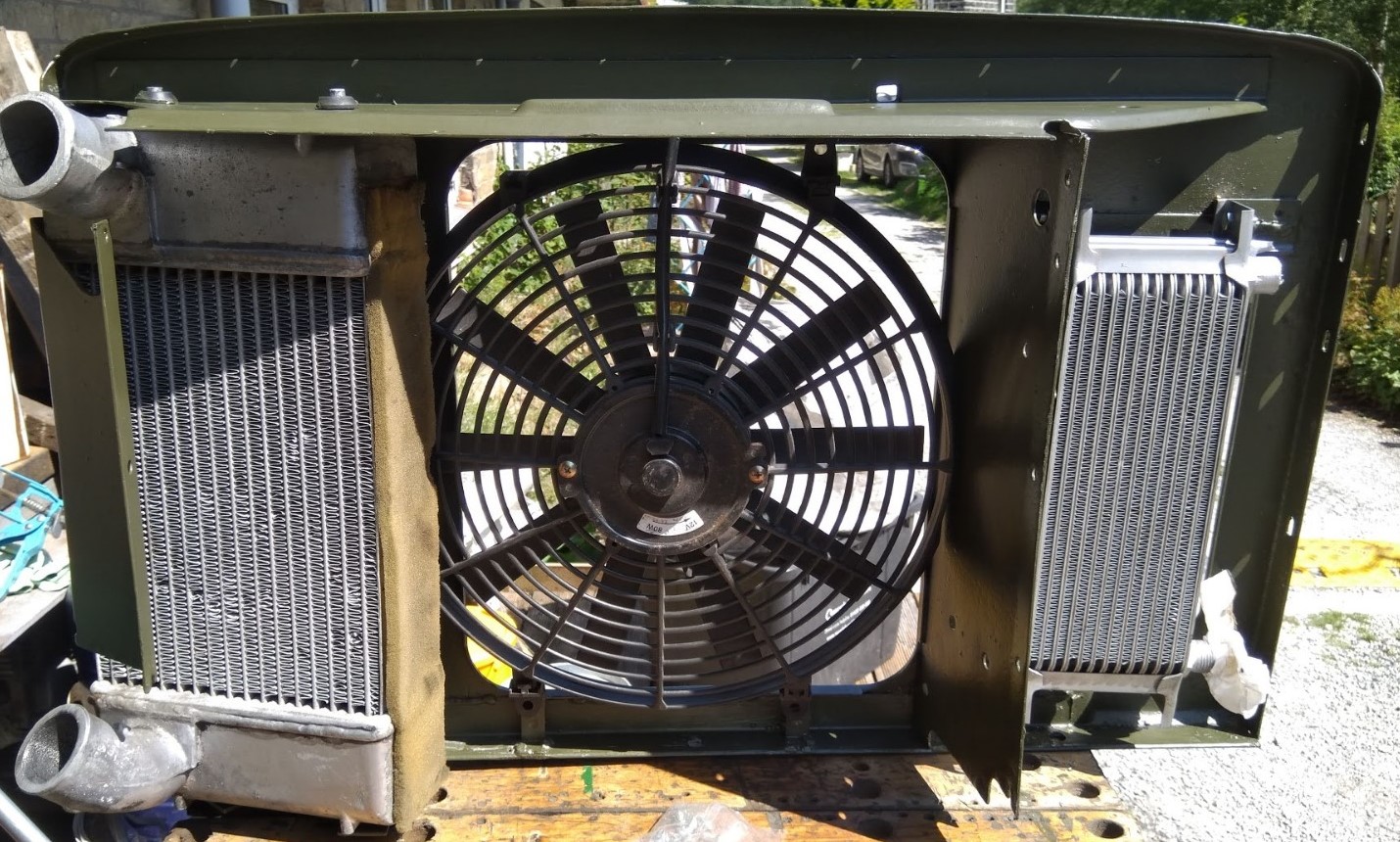
The headlights have relays and I am now moving them into a waterproof box along with a relay for the electric fan. 

For reference here is an extensive list of the cable colour codes for Series Land Rovers:

BLACK CABLE
Black/ Purple          – Temperature switch to warning light
Black/ Green           – Relay to radiator fan motor, windscreen wiper switch to single speed wiper motor.
Black/ Light Green  – Brake switch
Black/ Light Green  – Brake differential pressure valve to warning light
Black/Orange          – Radiator fan motor to thermal switch
Black/Red                – From 3 prong flasher unit to flasher light
Black/White             – Flasher unit light to ground


BLUE CABLE
Blue                       – Headlamp switch to dimmer switch
Blue White            – Headlight high beams, Dimmer switch to long-range driving light switch
Blue/ White            – High beam dimmer switch to high beam indicator lamp
Blue/ Light Green – Windscreen wiper switch to motor
Blue/ Red              – Headlight low beams
Blue/ Yellow          – Long range driving lamp switch to lamp

BROWN CABLE
Brown/Yellow           – GEN ‘D’ to volt. Regulator ‘D’. Ignition warning light
Brown/ Blue             – power feed to headlamp switch and voltage regulator to ignition switch
Brown/ White           – Ammeter to main alternator terminal, or voltage regulator
Brown/ Yellow          – Alternator to ‘no charge’ warning light
Brown/ Purple          – Alternator Regulator feed
Brown/ Green          – Fuse to horn (No relay), Generator ‘F’ to voltage regulator ‘F’
Brown/ Light Green – Windscreen wiper motor to switch
Brown/ Black           – Horn to horn button (no relay)

GREEN CABLE
Green/ Black    – Fuel gauge to fuel tank unit (Light green/black for vehicles with voltage stabilizer)
Green/ Orange – fuel low level warning light to sensor on fuel tank
Green/ Slate     – Heater motor to fast position on 2 speed heater switch
Green/ Blue      – Water temperature gauge to temperature sender unit (Light green/black for vehicles with voltage stabilizer)
Green/ Blue      – low fuel warning light to fuel sender unit.
Green/ Brown   – Switch to reverse lamp
Green/ Red       – Direction indicator switch to left-hand flasher lamps
Green/ Purple   – Stop lamp switch to stop lamps
Green/ White    – Direction indicator switch to right hand flasher lamps
Green/ Yellow   – Heater switch to slow speed on heater motor or for single speed motor
Green/ Yellow   – oil pressure light to oil pressure switch
Green/ Gray      – Heater switch to high speed on heater motor

LIGHT GREEN CABLE
Light Green              – choke cable mechanical switch to carburetter heater element (Solex optional fitment)
Light Green/ Black   – Windscreen washer switch to washer motor
Light Green/ Blue     – Flasher switch to left-hand flasher warning light
Light Green/ Yellow  – Flasher switch to right-hand flasher warning light
Light Green/ Brown  – Flasher switch to flasher unit ‘L’
Light Green/ Purple  – Flasher unit ‘F’ to flasher warning light
Light Green/ Orange – Rear window washer switch to motor
Light Green/ Red      – Fuel mixture light to fuel mixture thermostat switch (vech. with carb heater)

ORANGE CABLE
Orange/ Black          – Wiper switch to to motor parking
Orange/ Blue            – Wiper switch to low speed on motor
Orange/ Green         – Wiper switch to high speed on motor
Orange/ Yellow         – Rear wiper switch to rear wiper motor
Orange/ Light Green – switch to rear window motor parking

PURPLE CABLE
Purple/ Brown – Horn fuse to horn relay when horn is fused separately
Purple/ Red    – Switches to map light, under bonnet light, glove box light and boot lamp when fed direct from battery fuse

RED CABLE
Red/ Yellow  – Fog light switch to fog light or front fog light fuse to fog lights
Red/ Blue     – Front fog light fuse to fog light switch
Red/ Brown  – Rear fog guard switch to lamps
Red Orange – Power to rear fog guard lamp fuse
Red/ White   – Fuse to instrument lamp switch, Instrument panel lamps

WHITE CABLE
White               – Power to coil, fuse to cold running light (vech. w/o carb heater)
White               – Power to electric fuel pump
White/ Black   – Ignition coil to distributor
White/ Black   – Distributor side of coil to tach impulse sensor
White/ Black   – Mechanical choke cable mounted switch to cold running thermostat switch (1960’s vehicle without carb heater)
White/ Yellow  – Mechanical switch on choke cable to thermostat switch( in 1970’s, white black earlier)
White/ Brown  – Oil pressure switch to warning light or gauge
White/ Blue     – Cold running light to mechanical switch on choke cable (vehicle without carb heater) (light blue in 1970’s)
White/ Pink     – Ignition switch to radio fuse
White/ Red      – Ignition switch or starter switch to starter solenoid

YELLOW CABLE
Yellow             – Dynamo ‘D’ to voltage regulator ‘D’, Voltage regulator ‘D’ to gen. light on instrument panel
Yellow/ Green – Dynamo ‘F’ to control box ‘F’ Alternator field ‘F’ to control box ‘F


200tdi Timing Belt Replacement guide (from scratch)

The threads in the block and timing case have now been repaired with Helicoils and the timing case is back on the engine block. Now to replace the timing gear. This is where I’m up to, the cam shaft pulley has already been replaced:

Bare 200tdi timing case

The bolt that secure the pulley onto the camshaft has two O-Rings and these should really be replaced with the timing belt as they stop oil passing down the camshaft into the case.200tdi camshaft O-Ring seals

The cam shaft bolt can be safely undone by resting a large screwdriver against the camshaft timing pointer moulded into the timing cover and jamming it into the camshaft pully to stop it turning as you undo the nut. Torque back up the same way to 45nm.

The injection pump is locked with a 9.5mm diameter locking pin (or a drill bit in my case). The pump pulley is secured back on by a flange with three bolts. The holes for the bolts on the flange are slightly elongated to allow for slight movement of the injector pulley in either direction while the injector timing remains locked. This allows the pulley to move slightly as the belt is tensioned. At this stage the bolts should be set finger tight in the centre of the holes and will only be fully tightened once the belt has been correctly tensioned.

200tdi Injection pump locked 200tdi injection pump pulley


Make sure the engine is at TDC before removing the belt. It’s not the end of the world if you don’t, but can be a bit fiddly getting the timing marks to line up afterwards as the camshaft and crankshaft will now be moving independently of each other and you will need to turn them both at roughly the same time to avoid valves hitting pistons etc. In my case I forgot and needed to turn both clockwise to get the timing marks to line up. In the image below you can see the timing dot on the camshaft pulley (yellow arrow) and where is should be (red arrow) lined up with the pointer on the timing case. The crankshaft woodruff key key should line up with the arrow on the timing case. There is also timing mark on the flywheel that you can fit a pin into through a hole in the bottom of the bellhousing to lock the flywheel, however if your 200 is in a Series there is no access to this hole a the cross member blocks it. The timing case marks are accurate enough to fit the belt though, just make sure you haven’t moved the crank when fitting the belt.

200tdi timing case 200tdi crankshaft timing mark

The crank and camshafts are now at TDC and the injection pump is locked so the new belt can now be fitted. Fit the idler pulley and torque to 45NM.
Start by fitting the belt around the crank sprocket, use a piece of folded cardboard between the bottom of the timing case and the bottom of the crank sprocket to hold the belt in place, take it around the camshaft pulley then the injection pump pulley, take care to make sure the pulleys have not moved from their timing marks. Make sure the belt is tight, you may need to slighlty manipulate the pulleys to get the belt to fit correctly. Then fit the tensioner on it’s pivot point on the timing case, using a dial type torque wrench pull it upwards to 19NM for a new belt or 17NM for an old belt. While you are holding the tension fit the tensioner bolt and torque to 45NM.

200tdi timing belt torque

Now tighten the three injector pump bolts to 25NM and remove the locking pin.
Temporarily refit the crank nut and turn the engine over on the crank nut for two full revolutions back to TDC and check the timing marks are where they should be, the locking pin should be able to fit back in the injection pump (however don’t leave it there!). If you feel any resistance when turning the engine you may be a tooth out on one pulley, so stop and double check the timing marks. If  there is no resistance and all the timing marks line up perfectly then you’re all done and can proceed to refit the front cover. The crank nut will require 340nm so make sure you have a suitable torque wrench – I use a very large screwdriver to lock the flywheel against the case through the starter motor hole for this.


Getting there..

It’s been 18 months since my last update on this, however! the 200tdi engine was rebuilt last year and has resided in my kitchen for 12 months as I have not been able to find any time at all to refit it, due to my time taken up with converting my loft.

The engine is now back in the Landy at last and I’m slowly getting to the point of starting it as I still have very little spare time. I’ve corrected a number of issues from the time I swapped the engine in, replacing the 2.25 5MB petrol, mainly electrical and how the engine bay is set out.

The head has been cleaned up, valves reseated, new stem seals, injectors have been sent for cleaning and checking.

I’ve got rid of the 200tdi radiator/oil cooler unit and gone back to the original Series radiator which is till in very good condition (only used for 40k miles from new). I was never very happy with the way the 200tdi rad unit fitted in the engine bay and always seemed a bit scruffy. I’ve sourced a 300tdi intercooler (has the exit pipes on the left hand side of the unit – 200 are on the right hand side) which is now situated inside a galvanised Front panel, a slight modification was required on the panel. I have also fitted an aftermarket oil cooler on the other side.

Engine bay looks much more tidy now with more space. I’ve just had to remove the timing case again as I stripped three threads putting it back together, one that goes through to the water pump and into the block that has the long stud at the top, and two water pump bolts into the aluminium timing case. I’ve now repaired the threads using Helicoils and are now even stronger that before. All the other timing case threads have been cleaned with an M8 tap.

Just need to put the timing case back on, rad back on, fill with water (will be flushing a few times before filling with coolant) and get it started.

Modified Series 3 Front Panel

Modified Series 3 Front Panel


Modified Series 3 Front Panel

Modified Series 3 Front Panel

200tdi engine

200tdi engine


Modified Series 3 Front Panel

Modified Series 3 Front Panel

Bits for the putting the 200tdi back together


I’ve got the crankshaft back from the machine shop. The main journals were fine and did not require any work however the big end journals needed two grinds to .020 (0.5mm) to clear the scoring.
I’ve got new bearings, piston rings, and a spigot bush from Turner Engineering which appear to be the best quality at the best price. I’ve also got a load of other bits from LRseries and some odds from eBay. Still need to get a timing kit and a 3 hole head gasket.

200tdi crankshaft200tdi crankshaft

Cleaning up the block


Got a bit further with cleaning up the mess today. I’ve been using Gunk and a combination of wire and nylon brushes which are doing the trick. I will finish off with a wire brush in a drill and then eventually paint the block again. It should be silver, however I already have some gold engine enamel so it’s going to be gold! I’ll get the crankshaft back next week so once I know how much has been taken off I’ll be able to order the new con rod bearings.

HRC200 Defender Engine Block 2000tdi

HRC2020 Defender engine block 200tdi


200tdi strip down, crankshaft re-grind and new shells


Had a bit of a disaster before Christmas, while on the motorway in the 109 one of the oil cooler lines sprang a leak, the engine was very rough when I left the motorway however was still running so must have happened just before I was turning off. The engine bay was covered in oil, I filled it up again at a petrol station and it ran fine again so I carried on until I got home which was only a few miles. However on starting the engine from cold the next day it was clear there was something wrong. I did a compression test and got following results:

Cyl 1 380psi
Cyl 2 420psi
Cyl 3 320psi
Cyl 4 415psi

Obviously 1 & 3 have issues, however as the lowest readings are not next to each other this suggests the head gasket is fine and the problem is bottom end, more than likely the big end shells have been trashed due to oil starvation.

So I finally managed to find the time to remove the engine last week. As it’s a Defender variant 200tdi it has to be separated from the gearbox to be able to remove the ladder frame as some of the securing bolts are in the flywheel housing, so the engine has to come out. Once on a stand I removed the cylinder head and everything was fine there. I’ve cleaned up the valves and replaced the valve seals with new genuine parts that I already had as spares. The engine block is extremely dirty due being covered in oil so I will degrease it and paint the block in engine enamel later. The bores look ok, no scoring and a lot of the cross hatching is still visible. Phew.

200tdi engine block covered in oil

200tdi engine block covered in oil200tdi pistons and bores200tdi cylinder head

Got the sump off which was full of glitter, actually it should be described as a big pile of ground big end shells which confirmed my diagnosis. I unbolted the con-rod cap ends and the shells were indeed very trashed. Unfortunately the crankshaft journals have been scored as a result and will need a regrind. The mains however appear ok so I may have got away with just getting the big end journals done. The last pic below is one of the mains, the other three are big ends. I’m taking the crankshaft to the machine shop tomorrow.

200tdi sump full of damaged con rod shells

200tdi trashed big end shells200tdi crankshaft

200tdi crankshaft big end journal200tdi crankshaft big end journal200tdi crankshaft big end journal200tdi crankshaft main journal