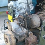
Since fitting the 200tdi I’ve decided to remove the Fairey Overdrive and fit a Ashcroft High Ratio Transfer Box. The overdrive raises the standard gearing by 27.5% over standard and the Ashcroft box raises the gearing by 31.8% which would suit the 200tdi fine, it is slightly lower than fitting 3.54 diffs but as I live in a very hilly area I think this will be the best compromise with the added benefit of the speedometer reading correctly and low range remaining unaffected. I find the Fairey Overdrive very noisy and I’ll be glad to get rid of it!
The gearbox currently fitted to my 109 is original to the Land Rover and is a Suffix D box. The synchros springs on 3/4 are long gone and I’ve been double de-clutching for the last year or so, I have a spare low mileage suffix D box that I’m going to fit the High Ratio Transfer Box to and then drop that into the 109 and replace the synchro springs on the old one when I get round to it and keep it as a spare.
Today I made a start – due to having a very young daughter my spare time is mainly spent doing family things these days so finding time for the Landy is proving difficult!! – I’ll update this post as I go along.

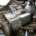
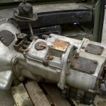
Series 3 Suffix D Gearbox
The Ashcroft High Ratio Kit is basically a reworked transfer box with three gears, 1 standard Input Gear, 1 Intermediate Gear and 1 High Range Output Gear plus a set of gaskets. The old transfer case needs to be removed from the gearbox, the gears swapped over and the new Ashcroft transfer case built back up and mated back up to the gearbox – the process of dismantling the transfer box is well documented in the green bible and the Haynes manual – it should be a straight forward job!
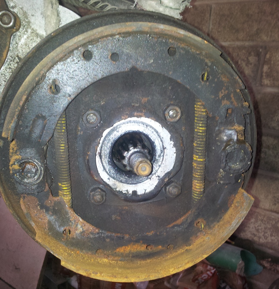
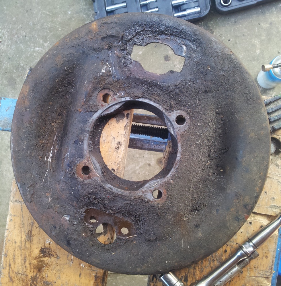
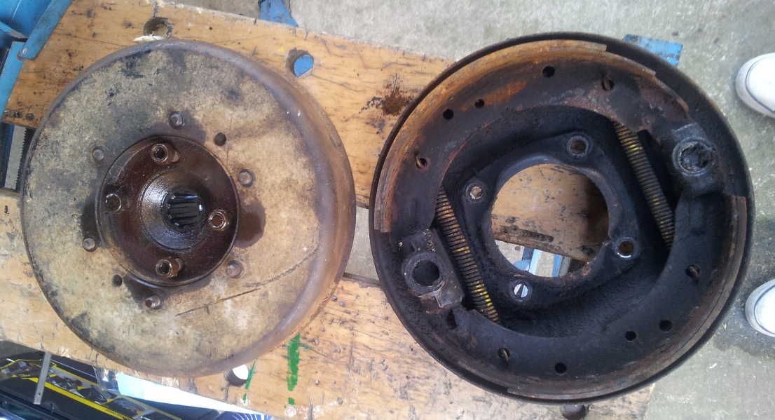
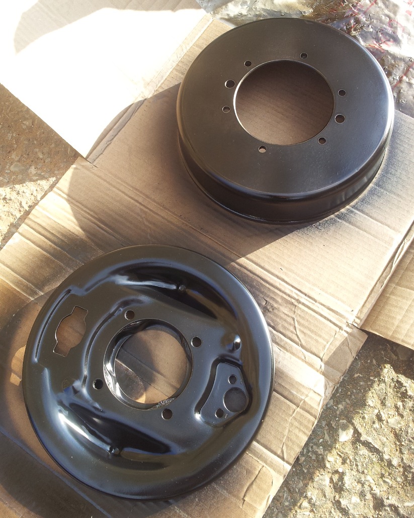
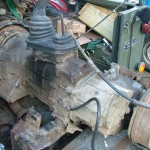
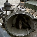
First job is to remove the transmission handbrake unit. This gearbox has been lying around for a number of years and the handbrake drum was seized. I managed to loosen off the adjuster screw and slackened it off as far as it would go and gave a few whacks with a rubber mallet and eventually the drum started turning and I could get the drum off. It’s pretty well gunked up so I’ll clean it all up before refitting. The whole unit comes off in one piece once the four nuts in the centre are removed.

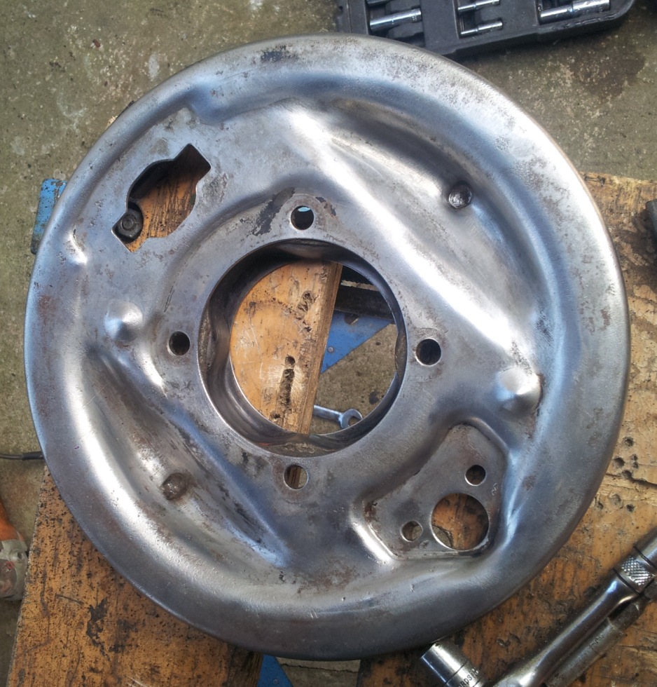
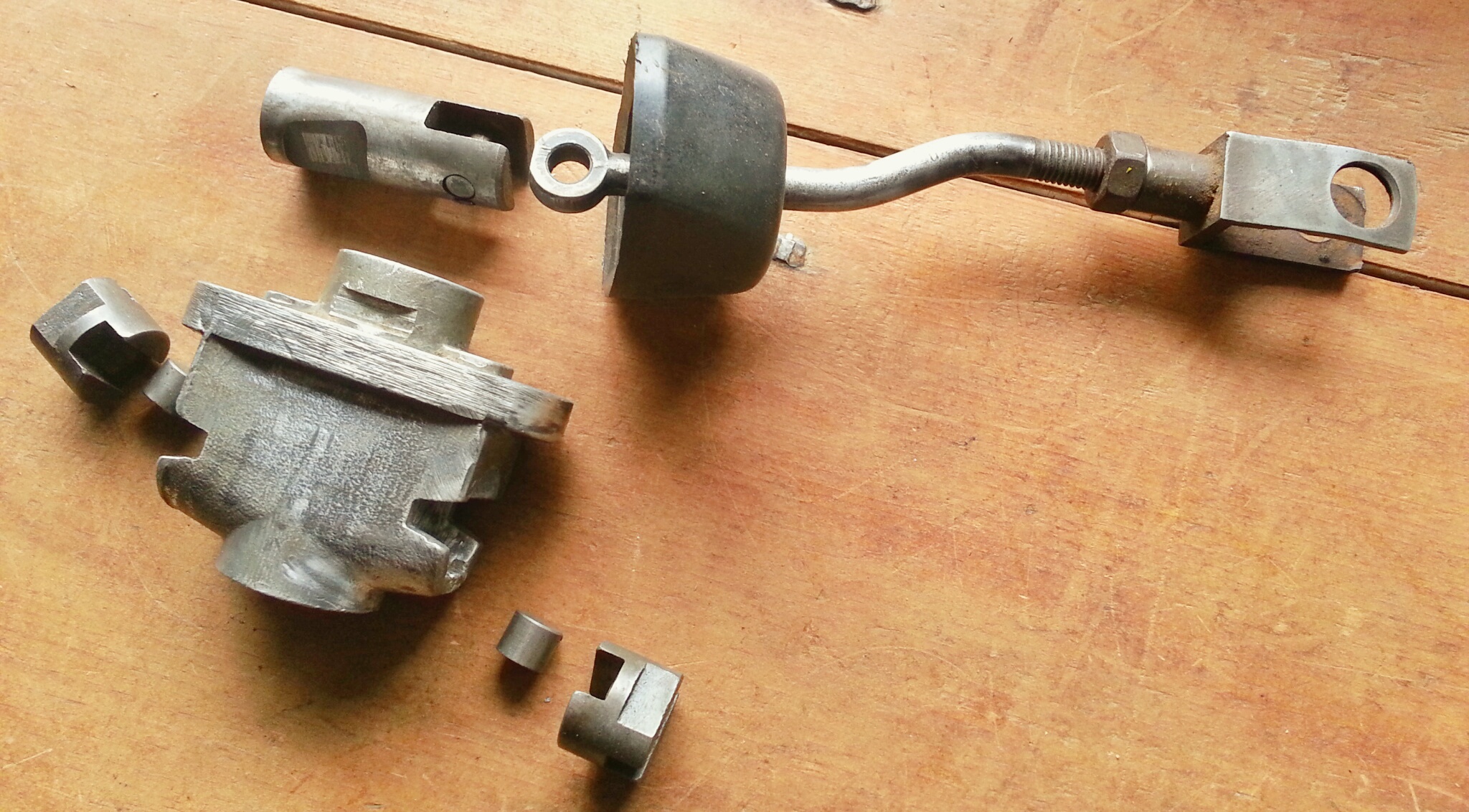
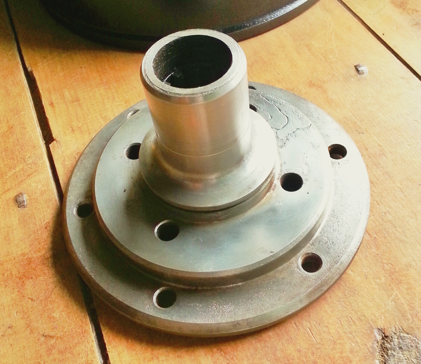
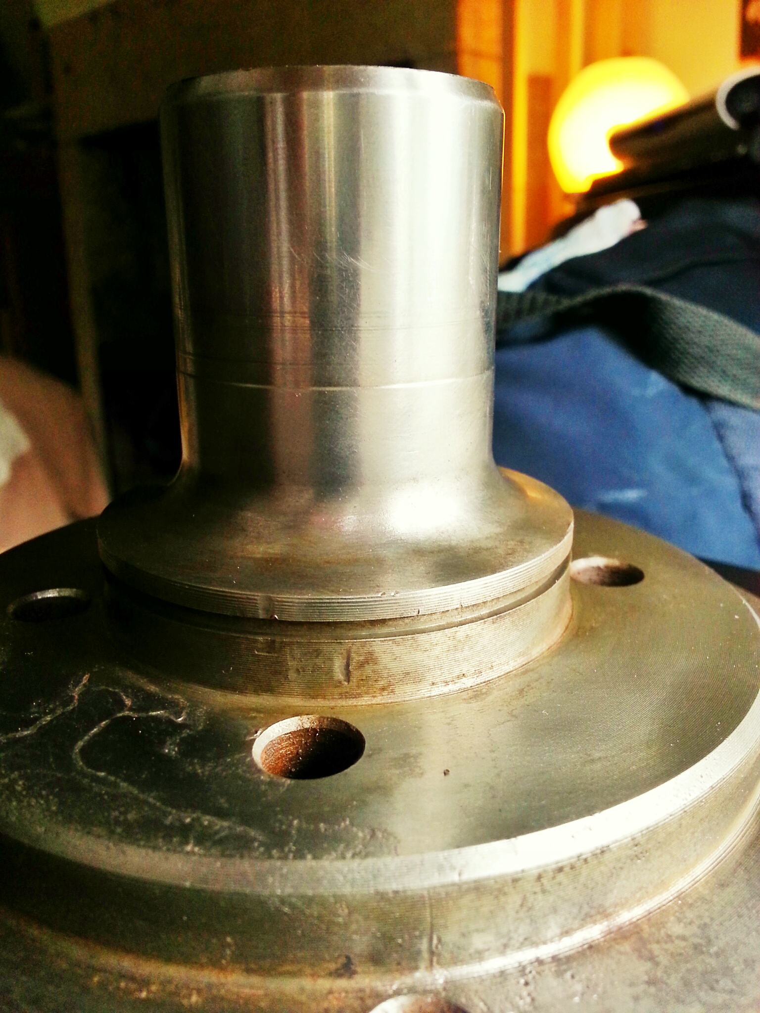
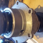
Once the handbrake drum and backplate is off you can get access to the speedo drive unit – remove the six nuts securing the unit and it comes straight off to reveal the speedo worm gear. The below photo shows the worm gear plus the speedo drive unit together.

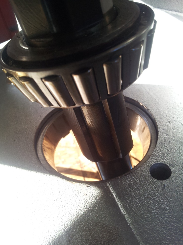
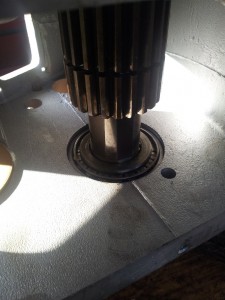
Next I removed the rear PTO cover and from there removed the mainshaft nut, locking washer and took out the input gear. The below photo shows the nut and gear through the inspection hole. Note the mainshaft nut looks to have been on and off in the past as it’s showing marks from being tightened up with a hammer and screwdriver or chisel. The correct tool to tighten this nut is Land Rover Special Tool 600300 which are quite hard to get hold of cheaply – I have a socket that I cut down with a grinder that fits the mainshaft castle nut and means I can torque it up accurately.

Once the input gear was removed I then removed the transfer box sump cover.

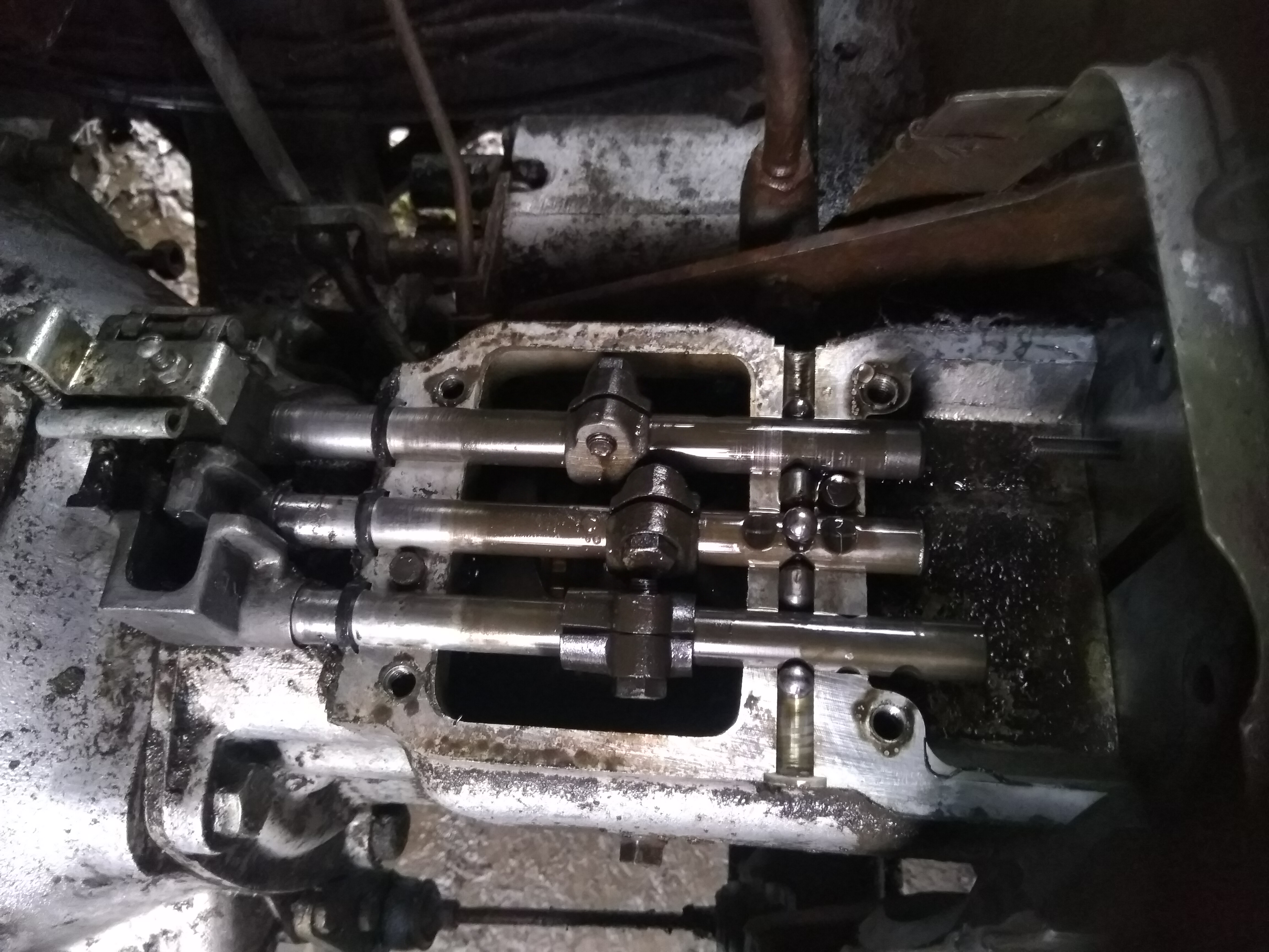
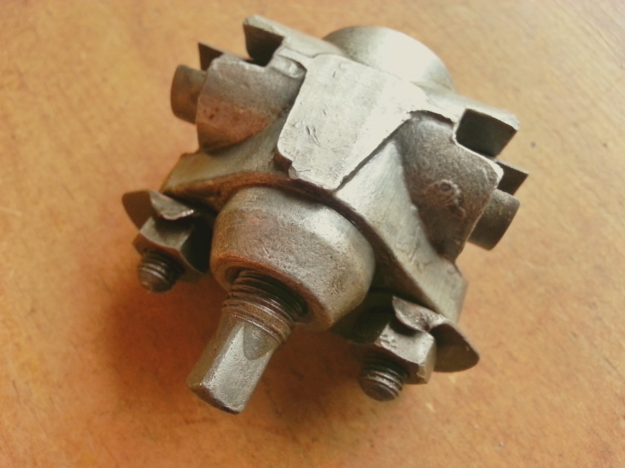
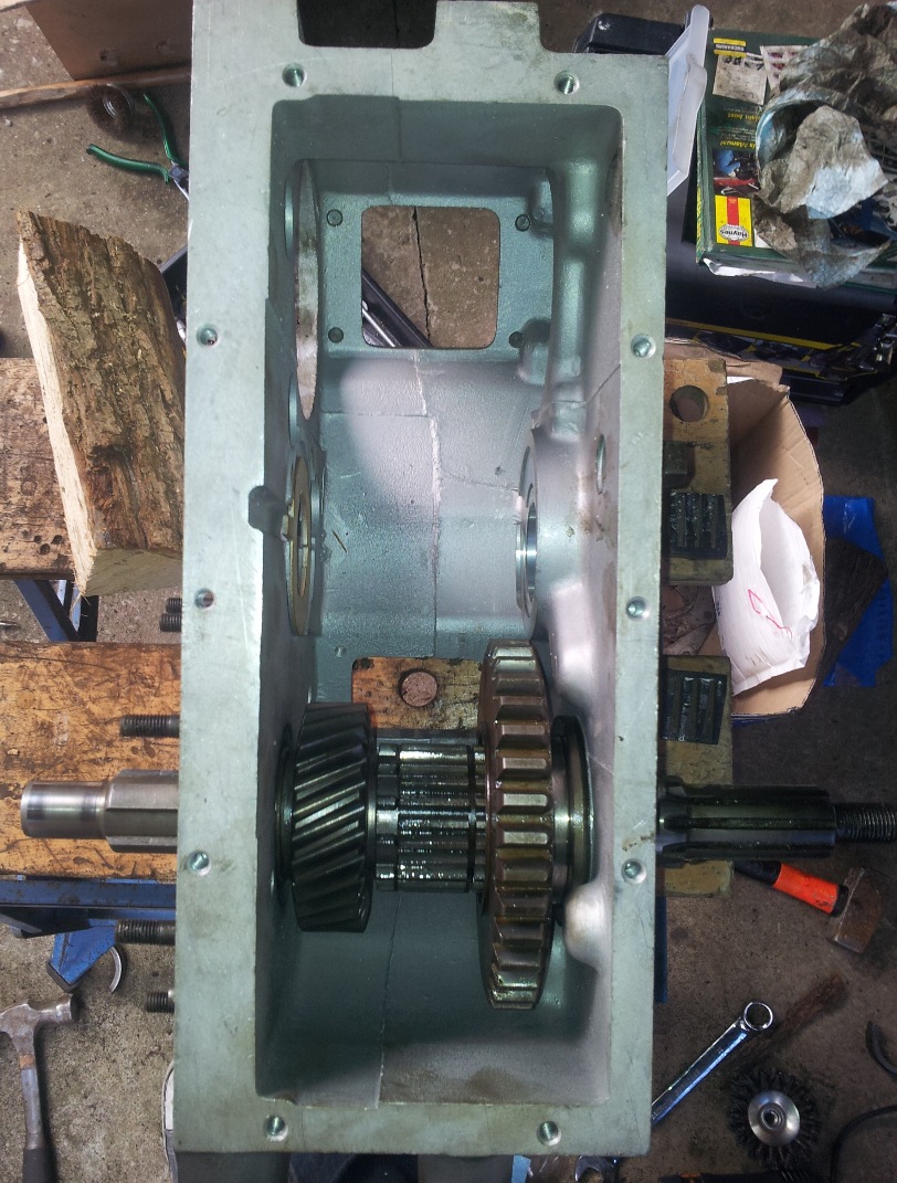
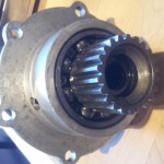
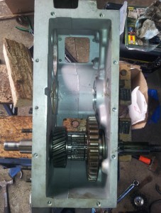
The intermediate gear (center gear in the above photo) now needs to be removed in order to access the three bolts inside the case that holds the transfer box to the gearbox. The intermediate shaft is held in place by a locking tab which is secured by a nut on the outside of the case – see photos below – you’ll need a crowbar to pull the shaft out, make sure you catch the intermediate gear as drops when the shaft is removed.


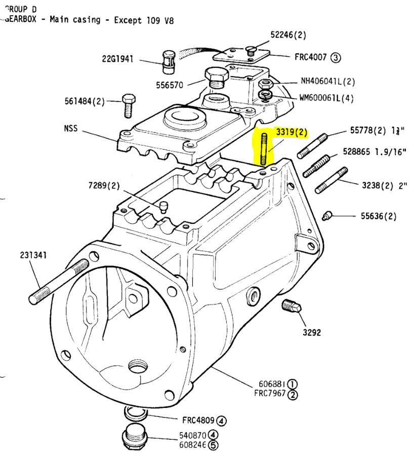
You can now access the three internal bolts holding the gearbox and transfer box together:

Once these are undone and the few other bolts on the outside of the case are removed the gearbox and transferbox will pull apart. As seperate items they are now much easy to handle and carry about.

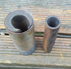
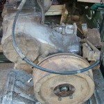
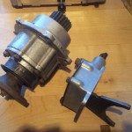
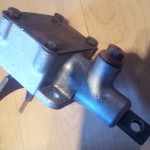
The below photo shows the new Ashcroft case alongside the old standard case.

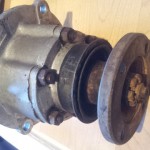
Next job is to remove the front output case. To do this remove the detent spring and plunger and pinch bolt for the selector shaft. Then remove the bolts connecting the case to the transfer box and the two just pull part easily.


All that’s left to do now is remove the main output shaft from the old transfer box and refit it into the Ashcroft box with the new high speed gear in place of the old one. The shaft is held in place by two bearing races and it can be quite tricky getting these out. The shaft has to be tapped backwards firstly and the bearing pushes the race out. In reality you’ll need to give it a fair bit of welly with a big hammer but use a deep socket over the end of the shaft to protect it from getting damaged by the hammer – I used a block of wood between to protect the end of the shaft. This process would benefit from heating the case around the bearing race.


Once the rear bearing race has been removed there is a bit of room to move the shaft about. You’ll need some circlip pliers to remove the circlip on the shaft, when you refit the circlip it should be replaced with a new one. Once the circlip is removed it is possible to slide the shaft out of the transfer box while catching the various parts as they come off. Once the shaft is removed you’ll need to remove the front bearing race from the case – again you could use the shaft and bearing to push this out but due to the amount of force needed to get the rear race out I decided to use something else to remove it – again I used a block of hardwood and heated the case around the race first and out it came. So now it is case of building it all back up in the new case.
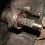
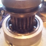
First job is to replace the large circlip that holds the front bearing race in, then push the bearing race into the new case up to the new circlip (I left both races in the freezer for a week before I did this and it did help a lot), again this takes a lot of force but it does go in eventually. Then place the output shaft in the new transfer case and replace the old high range output gear for the new Ashcroft high range gear and fit your new circlip. When the output shaft is built back up and in place then the rear bearing race should be pushed in to the transfer case to hold the shaft in place. It is important that the race takes up any play in the shaft but also does not apply any preload. If the shaft feels heavy to turn then you may have pushed the race in too far and it will need tapping from the front end again to take away any preload. Images below show the bearing on the shaft pushing the front race into the case.

Now the output shaft is in place then the next job is setting the preload on the output shaft – the preload is set by the speedo housing putting pressure on the rear bearing race which should be sitting very slightly proud of the case (if it is not sitting slightly proud you may have pushed the race in too far and this will be applying too much preload). In order to test the preload you’ll need a spring balance and something suitable to wrap around the selector groove on the high range gear such as nylon fishing line. The correct preload is set when the spring balance registers between 2-4lb force to turn the shaft. The preload can be altered by adding and removing the steel shims that sit between the speedo housing and the transfer case. Start with all the shims that you removed from your old transfer box and bolt up the speedo housing to the correct torque (12lbs ft), then test the preload with the spring balance, you’ll probably then have to remove a shim or two and bolt up the housing again before you get the correct preload setting. Better to start with too many shims as too little may give you too much preload and you’ll have tap the shaft back again to release the preload. I’ve heard of people having problems with this process but I found it quite simple and has worked fine. My preload is showing at just under 3lb which is fine. Once you are happy that the preload is ok then remove the speedo housing once more and replace the speedo worm gear and bolt it all back up.
One other thing – while the speedo housing is off the transfer case it is also worth replacing the seal as the genuine part is cheap and you will be annoyed to find it leaking there after all this work. It is much easier to replace the seal on the bench than under the Landy.
14/04/2013 – Whilst test fitting the intermediate shaft to check the end float I found it wouldn’t slide into the new hole unless I used way too much force and in fact broke the locking tabs off the end of the shaft by hitting it so hard – it should just slide in. On measuring the new hole I got an internal diamter 40.54mm, yet the shaft measures 41.15mm so there was no chance it was ever going to fit. I emailed Ashcrofts to let them know and to their credit they offered a replacement box and intermediate shaft as the old one was now useless. I had a spare shaft from a scrap transfer box I’m just going to use that and rather then dissemble the box again I have used a flap wheel on a Dremel to open out the hole slightly. The shaft now slides in nicely. If you are doing this conversion I would recommend checking the shaft fits as soon as you get the box as it may set you back some unexpected time if you don’t have the tools handy to fix it.
I’m now waiting for a replacement thrust washer to arrive as I managed to damage it whilst trying to get the shaft in/out. Will update when there is progress.