200tdi into a Series Land rover – which temp sender?


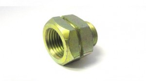
The problem here is the Discovery temperature sender in the 200tdi engine is not matched to the Series gauge so you will not get the correct temperature reading. The Series temperature sender (560794) does not physically fit into the 200tdi thermostat housing – so in order to use the original series temp sender you need to get an adaptor that screws into the 200tdi housing (ERC8973) and the series temp sender then screws into that.

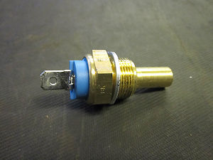
However Richard at www.glencoyne.co.uk has just discovered that the temperature senders that were fitted to the 200tdi Range Rover Classics are a direct fit but also a good match for the Series temp gauge. I have test fitted one and when the engine is fully hot the needle is just into the N mark. The part number is AMR1712 and looks the same as the Disco version but has a blue insulator.

ERC8973 Temp sender adaptor

ERC8973 Temp sender adaptor

AMR1712

AMR1712

Cleaning up the handbrake


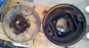
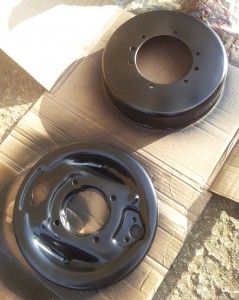
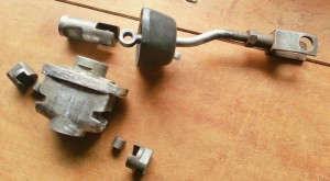
In between finding time to finish my high ratio transfer box I have cleaned up the handbrake on the replacement gearbox that I will be fitting shortly. The handbrake drum was seized and very gunked up, the actuator and adjuster were also seized solid.

Series 3 handbrakeHandbrake drum backplateHandbrake drum and back plate

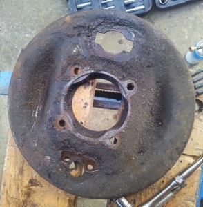
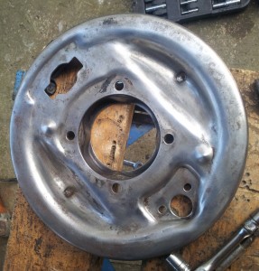
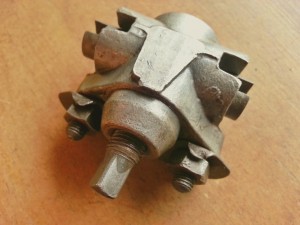
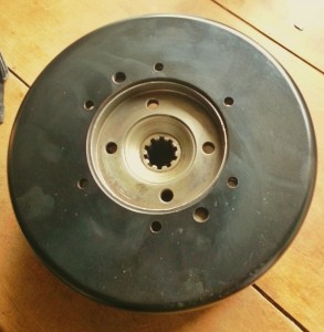
Using a knotted wheel on a 4.5″ angle grinder I cleanen up the drum and back plate and painted them both. I managed to unstick the calipers in the actuator and the adjuster and cleaned them up with a small wire wheel in a Dremel, I have greased the internals and they are now as good as new.

Handbrake backplatedpainted brake drum and backplateHandbrake ActuatorHandbrake Adjuster

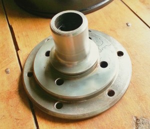
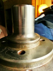
I have also cleaned up the output flange which has minimal wear and is ok to be reused. Sometimes the output flange can have a groove worn into them by the rear oil seal and this will lead to oil leaks as the seal cannot seal properly. If the flange is too worn then it should be replaced or you could fit a Speedi-Sleeve which is a thin walled sleeve that slides over the flange giving a level surface and they are cheaper than a new flange.

Output flangeOutput flangeOutput flange and brake drumOutput flange and brake drum

I’m happy with the result from an hours work – I’m now expecting a very effective and easily adjusted handbrake!


Replacing door hinges


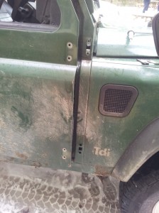
I was recently asked by the National Trust to replace the front door hinges on a Defender 300TDI 110 that is used on one of their nearby properties, so today I spent a couple of hours changing the hinges. The hinges on this model of Defender are exactly the same hinges that were used on my 1982 Series 3.

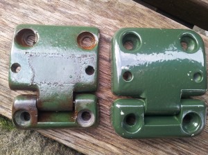
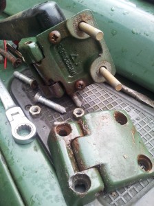
The drivers side door wouldn’t close on the latch as it had a lot of up/down play due to the hinges being very worn, turns out they were not the original hinges and have been replaced by Britpart hinges somewhere down the line – Britpart hinges are poor quality and have can have play in them from new! I managed to source a reasonably priced set of 4 genuine part hinges that I had to paint Coniston Green to match the 300TDI, the genuine hinges are much better quality. Below shows the old Britpart hinge on the left, new genuine on the right.
Britpart and genuine door hinges

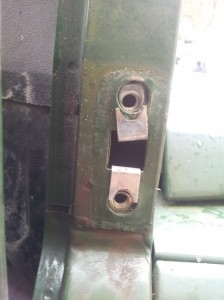
The hardest part of the job is removing the screws on the bulkhead side of the hinge as they tend to corrode and rust into the captive nuts in the bulkhead. If you are lucky they may just unscrew with a screwdriver but I’ve found usually they don’t. If they won’t budge with an impact screwdriver and you are reusing the hinge then you’ll need to drill out the head of the screw, then you can pull the hinge off and you’ll need to remove the remains of the screw and the captive nut from the bulkhead with some pliers, try not to let them drop into the bottom of the pillar as they will corrode down there and encourage corrosion in the pillar – if you do lose one inside the pillar use a magnet to retrieve it.

In my case I was replacing the hinges so I used a grinder to cut them off. The screws on the door side are much easier to remove as the nut is inside the door and tends not to be too rusty, remove the nut and screw will pull out. Once the old hinges are off it’s a straight forward job to put the new ones on. Fit new captive nuts, these are J-nuts with a hook that fits over the bulkhead as pictured below:

Bulkhead captive nutsbulkhead captive nuts

The hinges also have hard plastic gaskets that you should be able to reuse. There is quite a lot of room for adjustment of the door in the bulkhead side screws, attach the hinges and tighten the screws enough so they are tight but you can still move them about to adjust the hang of the door. I opened the window and held the door using the handle on the inside until it was sitting correctly then tightened up the screws with my other hand. The door now has no play and shuts and locks perfectly. The image below shows the top hinge with wing mirror attached.

door hinge


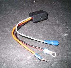
New thermostat & voltage stabiliser


My temperature gauge has been a bit erratic for a while and I’ve suspected the thermostat has been stuck open as the temp gauge takes ages to warm up, never gets past the N mark and then drops very low on long steady runs, if the thermostat is working correctly the needle should get up to temp and stay there. I removed the thermostat housing to find the old stat was stuck partially open so replaced it with a new genuine 88 degree thermostat (ERR2803). A stuck stat is not just an over cooling problem but it was not opening fully either so the engine could potentially get too hot.

With the new thermostat the engine seemed much happier and the heater was very warm. However after a couple of miles the temperature gauge needle was in the red. I have an infra red thermometer that you can point at an object and it tells you the temperature (highly recommend these, very helpful for all sorts of things) so I tested the thermostat housing and it was showing 88 degrees, which is more or less the normal operating temp for a 200TDI so obviously the guage was reading incorrectly. I have a series temp sender in the 200TDI with the adaptor for the TDI engine so that should be matched to the Series guage ok. While opening up the clocks in the dash I found the voltage stabilser was loose in the back, it should be bolted to the back of the speedo as the casing itself needs earthing for it to work correctly. The stabiliser should give a steady 10v to the temp and fuel gauges, as the voltage from the alternator can vary, therefore you’d have varying guage readings depending on the voltage so the stabiliser’s job is to give a steady 10v. As my stabilser was giving the full alternator voltage (13.7v in my case) to the temperature and fuel gauge they were therefore over reading. Once the stabilser was earthed again the temp gauge was reading normal at the correct operating temperature as it should. The bad news is I had less fuel than I thought I had!

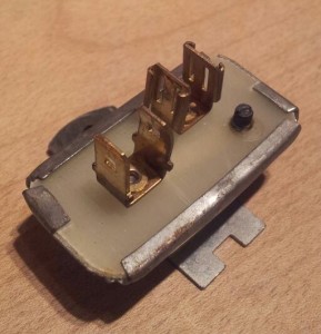
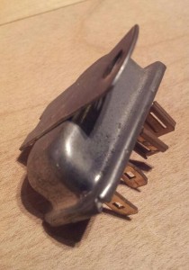
Below are pics of the standard series 3 voltage stabliser that should be bolted to the back of the speedo, there are a set of two female connectors and a set of two male. The positive from the fuse box goes to one male spade and one female spade (supplying 10v) goes to the temperature gauge and from there onto the temperature guage. As mentioned before the case needs to earthed for it to work correctly.

Series 3 Voltage StabilserSeries 3 Voltage Stabiliser

While I was at it I decided to upgrade the stabiliser to a solid state modern version that is a bit more reliable and accurate, bought this one on eBay for a tenner – it is a direct replacement & a five minute job to swap over:

new solid state voltage stabilser

Removing a Steering Wheel


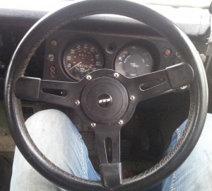
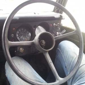
Had five minutes spare today so decided to swap the steering wheel on the 109 – it’s had a 15″ Mountney steering wheel ever since I bought the Land Rover but I’ve found the steering can be a little heavy due to the smaller wheel diameter. I bought replacement standard wheel on eBay ages ago but haven’t got round to swapping them until now.

Series 3 Land Rover Mountney Steering Wheel

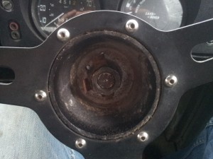
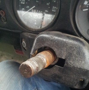
Simple job to do, I prised the centre boss out of the steering wheel which reveals the large nut and locking washer. In my case the locking washer wasn’t locking anything and the nut was finger tight! A 1-1/16 socket fits the nut perfectly.

Land Rover Series 3 Steering Wheel nut and locking washer

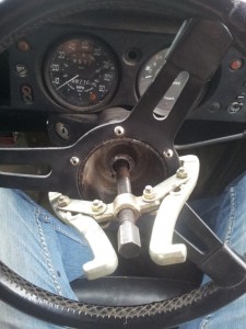
You may find the steering wheel is still stuck to the column after removing the nut, I had to use a puller to get it off. If you try pulling it off with your hands, leave the nut on a few threads so it doesn’t hit you in the face when it pops off!!

Using a puller to remove the steering wheelTop of steering column with wheel removed

Here’s the new/old standard series wheel fitted. I think this is the wrong wheel for my vehicle year (1982) but it looks fine all the same.

Land rover series 3 Steering Wheel

Just need to buy a new locking washer as the old one was in poor condition. After going for a test drive I wish I’d swapped wheels years ago, the steering is much lighter now. the Mountney steering wheels are probably fine for an 88 but I think the 109s need the wider wheel.

Fitting a High Ratio Transfer Case


Since fitting the 200tdi I’ve decided to remove the Fairey Overdrive and fit a Ashcroft High Ratio Transfer Box. The overdrive raises the standard gearing by 27.5% over standard and the Ashcroft box raises the gearing by 31.8% which would suit the 200tdi fine, it is slightly lower than fitting 3.54 diffs but as I live in a very hilly area I think this will be the best compromise with the added benefit of the speedometer reading correctly and low range remaining unaffected. I find the Fairey Overdrive very noisy and I’ll be glad to get rid of it!

The gearbox currently fitted to my 109 is original to the Land Rover and is a Suffix D box. The synchros springs on 3/4 are long gone and I’ve been double de-clutching for the last year or so, I have a spare low mileage suffix D box that I’m going to fit the High Ratio Transfer Box to and then drop that into the 109 and replace the synchro springs on the old one when I get round to it and keep it as a spare.

Today I made a start – due to having a very young daughter my spare time is mainly spent doing family things these days so finding time for the Landy is proving difficult!! – I’ll update this post as I go along.
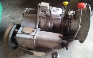
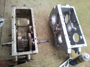
Series 3 Suffix D Gearbox

Series 3 Suffix D Gearbox

The Ashcroft High Ratio Kit is basically a reworked transfer box with three gears, 1 standard Input Gear, 1 Intermediate Gear and 1 High Range Output Gear plus a set of gaskets. The old transfer case needs to be removed from the gearbox, the gears swapped over and the new Ashcroft transfer case built  back up and mated back up to the gearbox – the process of dismantling the transfer box is well documented in the green bible and the Haynes manual – it should be a straight forward job!

First job is to remove the transmission handbrake unit. This gearbox has been lying around for a number of years and the handbrake drum was seized. I managed to loosen off the adjuster screw and slackened it off as far as it would go and gave a few whacks with a rubber mallet and eventually the drum started turning and I could get the drum off. It’s pretty well gunked up so I’ll clean it all up before refitting. The whole unit comes off in one piece once the four nuts in the centre are removed.
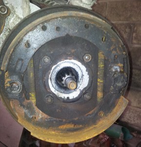
Series 3 handbrake

Once the handbrake drum and backplate is off you can get access to the speedo drive unit – remove the six nuts securing the unit and it comes straight off to reveal the speedo worm gear. The below photo shows the worm gear plus the speedo drive unit together.
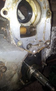
Series 3 Speedo worm gear and drive

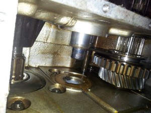
Next I removed the rear PTO cover and from there removed the mainshaft nut, locking washer and took out the input gear. The below photo shows the nut and gear through the inspection hole. Note the mainshaft nut looks to have been on and off in the past as it’s showing marks from being tightened up with a hammer and screwdriver or chisel. The correct tool to tighten this nut is Land Rover Special Tool 600300 which are quite hard to get hold of cheaply – I have a socket that I cut down with a grinder that fits the mainshaft castle nut and means I can torque it up accurately.
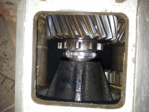
Mainshaft nut and input gear

Once the input gear was removed I then removed the transfer box sump cover.
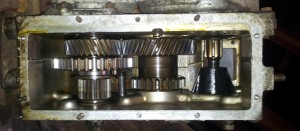
Series 3 Transfer box internals

The intermediate gear (center gear in the above photo) now needs to be removed in order to access the three bolts inside the case that holds the transfer box to the gearbox. The intermediate shaft is held in place by a locking tab which is secured by a nut on the outside of the case – see photos below – you’ll need a crowbar to pull the shaft out, make sure you catch the intermediate gear as drops when the shaft is removed.
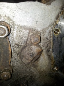
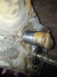
Intermediate shaft locking tabIntermediate shaft removaltransfer box with intermediate gear removed

You can now access the three internal bolts holding the gearbox and transfer box together:
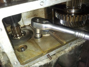
gearbox/transfer box connecting bolts

Once these are undone and the few other bolts on the outside of the case are removed the gearbox and transferbox will pull apart. As seperate items they are now much easy to handle and carry about.
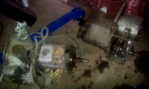
Series 3 gearbox and transfer box separated

The below photo shows the new Ashcroft case alongside the old standard case.
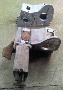
Land Rover Series Ashcroft high ratio transfer case

Next job is to remove the front output case. To do this remove the detent spring and plunger and pinch bolt for the selector shaft. Then remove the bolts connecting the case to the transfer box and the two just pull part easily.
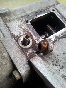
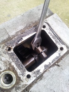
Removing the selector shaft detent spring and plungerRemoving the pinchbolt for the selector shaftStandard series transfer box with Ashcroft box

All that’s left to do now is remove the main output shaft from the old transfer box and refit it into the Ashcroft box with the new high speed gear in place of the old one. The shaft is held in place by two bearing races and it can be quite tricky getting these out. The shaft has to be tapped backwards firstly and the bearing pushes the race out. In reality you’ll need to give it a fair bit of welly with a big hammer but use a deep socket over the end of the shaft to protect it from getting damaged by the hammer  – I used a block of wood between to protect the end of the shaft. This process would benefit from heating the case around the bearing race.
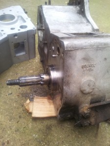
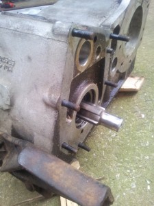
Pushing the bearing race out using the output shaftTap the output shaft backwards to push out the rear bearing race

Once the rear bearing race has been removed there is a bit of room to move the shaft about. You’ll need some circlip pliers to remove the circlip on the shaft, when you refit the circlip it should be replaced with a new one. Once the circlip is removed it is possible to slide the shaft out of the transfer box while catching the various parts as they come off. Once the shaft is removed you’ll need to remove the front bearing race from the case – again you could use the shaft and bearing to push this out but due to the amount of force needed to get the rear race out I decided to use something else to remove it – again I used a block of hardwood and heated the case around the race first and out it came. So now it is case of building it all back up in the new case.


First job is to replace the large circlip that holds the front bearing race in, then push the bearing race into the new case up to the new circlip (I left both races in the freezer for a week before I did this and it did help a lot), again this takes a lot of force but it does go in eventually. Then place the output shaft in the new transfer case and replace the old high range output gear for the new Ashcroft high range gear and fit your new circlip. When the output shaft is built back up and in place then the rear bearing race should be pushed in to the transfer case to hold the shaft in place. It is important that the race takes up any play in the shaft but also does not apply any preload. If the shaft feels heavy to turn then you may have pushed the race in too far and it will need tapping from the front end again to take away any preload. Images below show the bearing on the shaft pushing the front race into the case.
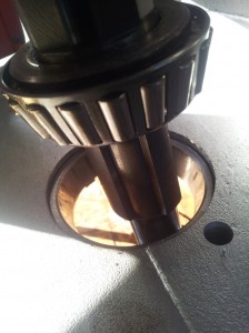
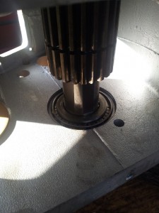
efrefiitting the front bearing racePushing the front bearing race in

Now the output shaft is in place then the next job is setting the preload on the output shaft  – the preload is set by the speedo housing putting pressure on the rear bearing race which should be sitting very slightly proud of the case (if it is not sitting slightly proud you may have pushed the race in too far and this will be applying too much preload). In order to test the preload you’ll need a spring balance and something suitable to wrap around the selector groove on the high range gear such as nylon fishing line. The correct preload is set when the spring balance registers between 2-4lb force to turn the shaft. The preload can be altered by adding and removing the steel shims that sit between the speedo housing and the transfer case. Start with all the shims that you removed from your old transfer box and bolt up the speedo housing to the correct torque (12lbs ft), then test the preload with the spring balance, you’ll probably then have to remove a shim or two and bolt up the housing again before you get the correct preload setting. Better to start with too many shims as too little may give you too much preload and you’ll have tap the shaft back again to release the preload. I’ve heard of people having problems with this process but I found it quite simple and has worked fine. My preload is showing at just under 3lb which is fine. Once you are happy that the preload is ok then remove the speedo housing once more and replace the speedo worm gear and bolt it all back up.

One other thing – while the speedo housing is off the transfer case it is also worth replacing the seal as the genuine part is cheap and you will be annoyed to find it leaking there after all this work. It is much easier to replace the seal on the bench than under the Landy.
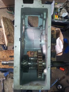
The output shaft and new high range gear in the new transfer case

14/04/2013 – Whilst test fitting the intermediate shaft to check the end float I found it wouldn’t slide into the new hole unless I used way too much force and in fact broke the locking tabs off the end of the shaft by hitting it so hard – it should just slide in. On measuring the new hole I got an internal diamter 40.54mm, yet the shaft measures 41.15mm so there was no chance it was ever going to fit. I emailed Ashcrofts to let them know and to their credit they offered a replacement box and intermediate shaft as the old one was now useless. I had a spare shaft from a scrap transfer box I’m just going to use that and rather then dissemble the box again I have used a flap wheel on a Dremel to open out the hole slightly. The shaft now slides in nicely. If you are doing this conversion I would recommend checking the shaft fits as soon as you get the box as it may set you back some unexpected time if you don’t have the tools handy to fix it.

I’m now waiting for a replacement thrust washer to arrive as I managed to damage it whilst trying to get the shaft in/out. Will update when there is progress.
Why is there oil in the air filter?


Series Land Rovers have a very effective oil bath air filter system that was been designed to work in jungles and deserts all over the world in all sorts of unpleasant conditions. If you’re off for a jaunt round the Sahara then the original oil bath filter is the one to keep. The oil bath catches larger particles from the inertia of the air changing direction quickly inside the filter housing, also, with the movement of the vehicle the oil splashs the mesh and this catches the finer particles as the air bounces through it. It is important not to overfill the oil past the level marker as you run the risk of sucking oil into the intake and into the engine which at best would result in rough running and a lot of black smoke, at worst with a diesel you could have a runaway engine as the engine starts to run on the oil. Obviously not enough oil will mean the filter is not working as effectively as it should. Changing and checking the oil in the air filter should be included in your regular sevicing of the vehicle as well as cleaning out the mesh with petrol.
Series Land Rover Speedometers


Suspect your speedometer may not be reading accurately?

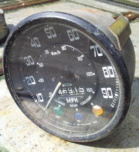
There are three different types of speedometers that are matched to the tyre size of the Land Rover – The standard tyre size on a Land Rover 109 was 750×16 and the standard tyre size on an 88 was 600×16, therefore the speedo would need to be calibrated differently for the tyre size on the vehicle. A 109 should have the code 1408 on the face (1408 turns per mile) and an 88 speedo with 600×16 tyres should have the code 1536 (1536 turns per mile).

Therefore if you have an 88 that has 750×16 or metric equivalent tyres with the original speedometer, it is likely to be reading inaccurately. The following info shows which speedo code matches which tyre:

1408 7.50×16 (235/85 r16)
1504 6.50×16 (205/80 r16)
1536 6.00×16 (205/70 r16)

Series Land Rover 109 Speedometer 1408

Series Land Rover Gearbox Rebuild parts list


For reference, here’s a list of all the bearings, seals, o-rings, bushes, gaskets, springs washers ie. everything you need to rebuild a Series Gearbox apart from the actual gears. A couple of years ago I priced it all up to just over £300 inc vat for all genuine parts – they’ll probably cost a bit more now.

1645           Rear Main shaft Bearing   (x1)
2422           Split pin for 4WD clevis fork  (x2)
PS608101  Split Pin for Output castle nut (x2)
5852           Selector ball spring rubber sealing ring (x2)
RTC1956   3/4 Syncro Detent Spring  (x3)
6397           Needle Roller Bearing (x1)
6405           Peg Main shaft Spacer (x1)
55714         Bearing Primary Pinion (x1)
211502       Speedo Drive Oil Seal (x1)
217325       Output Shaft Bearing (x1)
217476       Main shaft lock washer (x1)
217478       Rear main shaft bearing (x1)
217490       Front of transfer output shaft bearing (x1)
231116        Reverse stop gate spring (x2)
236305       Main shaft oil seal (x1)
FRC1780   Output shaft oil seal (x2)
243714       Clip for transfer lever
267828       O-ring for speedometer pinion and inter shaft  (x2)
272596       O-ring for forward selector shafts (x2)
272597       O-ring for reverse gear selector shaft  (x1)
528683       Front layshaft bearing retainer lock tab (x1)
528701       Front layshaft bearing (x1)
532323       O-ring for intermediate shaft (x1)
571059       Clutch sleeve housing oil seal (x1)
599869       Transfer box intermediate gear needle roller bearing (x2)
600603       Full gasket set  (x1)
622042       Output shaft felt seal
90217512   Output shaft rear bearing (x1) genuine part no longer available
FRC4076   Main shaft 2nd Speed gear bush (x1)
FRC4077   Main shaft 3rd speed gear bronze bush (x1)
RTC1412   Rear layshaft bearing (x1)
RTC1979   Peg for 2nd gear thrust washer (x1)

I’m pretty certain that’s a definitive list but feel free to let me know if I’ve missed anything.


Battery re-location after engine conversion

After I installed the 200tdi I had to find somewhere else to put the battery as the standard Series 3 chassis battery tray has to be removed to make way for the 200tdi timing case. I’ve got twin fuel tanks under the driver and passenger seats as the land rover is ex-mod so I was unable to put the battery under the passenger seat. I thought about putting the battery in the rear tub but in the end decided to fix an ammunition box in front of the radiator between the dumb irons, it’s been there for the last two years without problem.

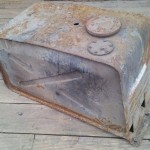
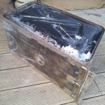
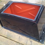
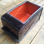
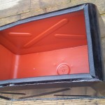
However I’ve always felt the battery was a little exposed there and also too easy for someone to steal, so I’ve decided to use the passenger side fuel tank to house the battery. The tank has not been used since it was in service as far as I know, and the change over tap is missing. The tank was fairly corroded but still water tight,  so I have cleaned it up, cut a section of the top out and painted it.